• Home
  • Download PDF
  • Order CD-ROM
  • Order in Print
Figure 15. Harness Retaining Hardware Inside Frame.
Figure 17. Chassis Harness Ground Connector Behind Hydraulic Oil Filter Base.

Field Maintenance Manual 2 D6K Dozer Type I With Winch and Type II With Ripper
Page Navigation
  1030    1031    1032    1033    1034  1035  1036    1037    1038    1039    1040  
img
.
TM 5-2410-240-23-2
0154
INSTALLATION CONTINUED
N OT E
Install electrical connectors and tiedown straps as noted during removal.
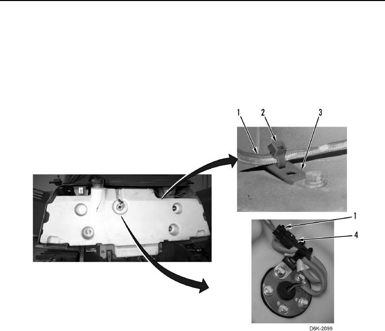
13. Connect chassis harness (Figure 16, Item 1) to fuel level sensor (Figure 16, Item 4).
14. Install four new tiedown straps (Figure 16, Item 2) on chassis harness (Figure 16, Item 1) and clips (Figure 16,
Item 3).
Figure 16. Fuel Level Sensor, Chassis Harness, and Retaining Hardware on Fuel Tank.
0154
0154-16


Privacy Statement
Press Release
Contact

© Copyright Integrated Publishing, Inc.. All Rights Reserved.