
TM 5-2410-240-23-2
0166
LEFT DRIVE LOOP FILTER AND WINCH FILTER BASE REMOVAL CONTINUED
N OT E
Note location of oil filter bypass switch, pressure tap, and fittings to aid installation.
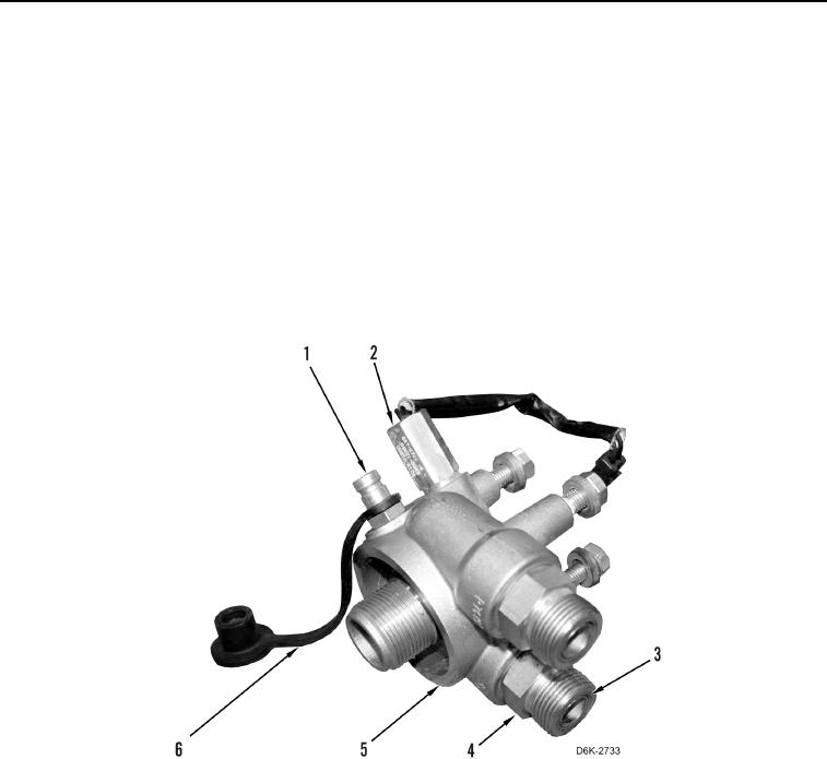
6. Remove oil filter bypass switch (Figure 2, Item 2) from filter base (Figure 2, Item 5).
7. Remove two O-rings (Figure 2, Item 3) from oil filter bypass switch (Figure 2, Item 2). Discard O-rings.
8. Remove cap (Figure 2, Item 6) from pressure tap (Figure 2, Item 1).
9. Remove pressure tap (Figure 2, Item 1) from filter base (Figure 2, Item 5).
10. Remove O-ring (Figure 2, Item 3) from pressure tap (Figure 2, Item 1). Discard O-ring.
11. Remove two fittings (Figure 2, Item 4) from filter base (Figure 2, Item 5).
12. Remove four O-rings (Figure 2, Item 3) from two fittings (Figure 2, Item 4). Discard O-rings.
Figure 2. Filter Base, Oil Filter Bypass Switch, Pressure Tap, Cap, Fittings and O-rings.
0166
END OF TASK