
TM 5-2410-240-23-2
0166
LEFT DRIVE LOOP FILTER AND WINCH FILTER BASE REMOVAL
000166
C AU T I O N
Cap or plug hydraulic tubes and fittings during removal to protect against contamination.
Failure to follow this caution may result in damage to equipment.
N OT E
This procedure covers removal of filter base for left drive loop filter. Follow the same
procedure when removing filter base for winch filter.
Tag and mark tubes, fittings, and electrical connectors to aid installation.
Note location of tiedown strap and orientation of clip to aid installation.
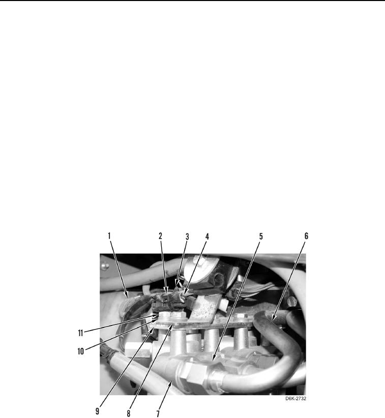
1. Remove tiedown strap (Figure 1, Item 2) from chassis harness (Figure 1, Item 1) and clip (Figure 1, Item 3).
Discard tiedown strap.
2. Disconnect oil filter bypass switch (Figure 1, Item 4) from chassis harness (Figure 1, Item 1). Position chassis
harness aside.
3. Loosen two tube nuts (Figure 1, Item 5).
4. Remove three bolts (Figure 1, Item 11), washers (Figure 1, Item 10), one bracket (Figure 1, Item 8), clip
(Figure 1, Item 3), and filter base (Figure 1, Item 7) from hydraulic system filter base bracket (Figure 1, Item 9).
5. Disconnect two tubes (Figure 1, Item 6) from filter base (Figure 1, Item 7).
Figure 1. Filter Base and Retaining Hardware.
0166