
TM 5-2410-240-23-2
0165
HYDRAULIC SYSTEM FILTER BASE INSTALLATION CONTINUED
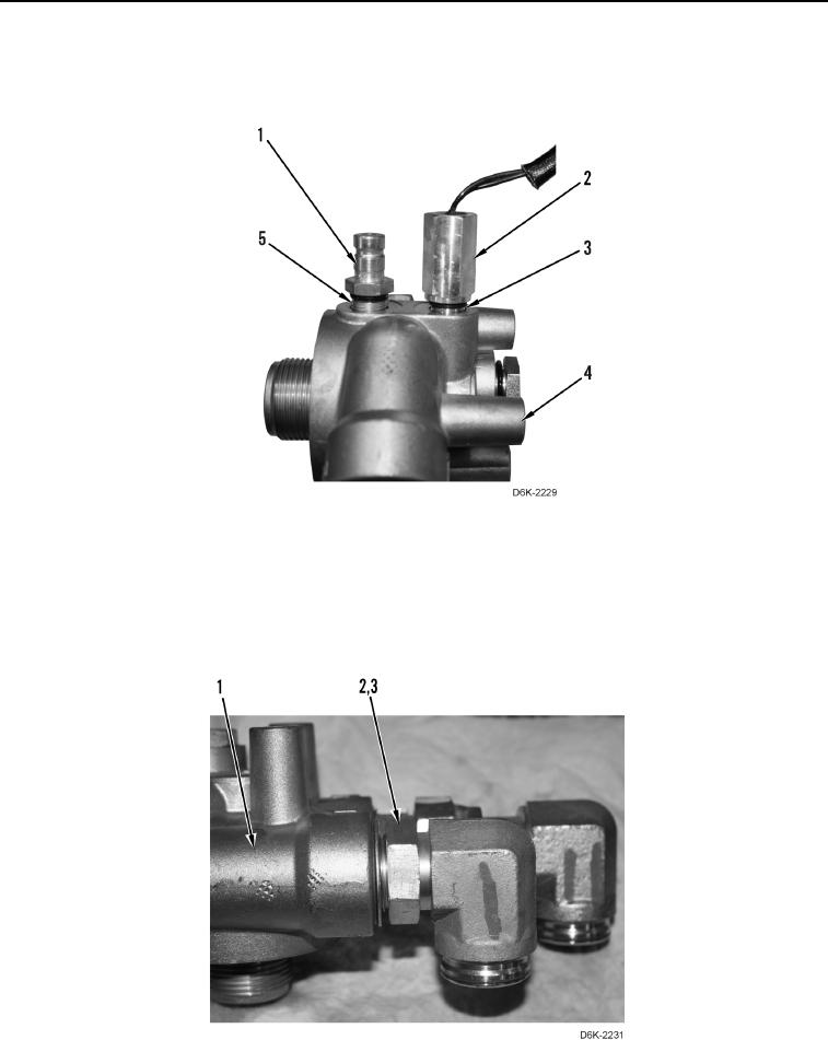
3. Install new O-ring (Figure 11, Item 5) and pressure tap (Figure 11, Item 1) on filter base (Figure 11, Item 4).
4. Install new O-ring (Figure 11, Item 3) and sensor (Figure 11, Item 2) on filter base (Figure 11, Item 4).
Figure 11. Pressure Tap, Sensor, and Base.
0165
N OT E
Install elbows as noted during removal.
5. Install two new O-rings (Figure 12, Item 3) and elbows (Figure 12, Item 2) on filter base (Figure 12, Item 1).
Figure 12. Base and Elbows.
0165