• Home
  • Download PDF
  • Order CD-ROM
  • Order in Print
Figure 4. Base and Elbows.
Figure 6. Tee, Connector, and Base.

Field Maintenance Manual 2 D6K Dozer Type I With Winch and Type II With Ripper
Page Navigation
  1164    1165    1166    1167    1168  1169  1170    1171    1172    1173    1174  
img
.
TM 5-2410-240-23-2
0165
HYDRAULIC SYSTEM FILTER BASE REMOVAL CONTINUED
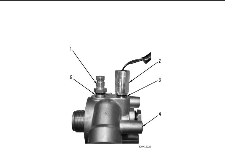
8. Remove sensor (Figure 5, Item 2) and O-ring (Figure 5, Item 3) from filter base (Figure 5, Item 4). Discard
O-ring.
9. Remove pressure tap (Figure 5, Item 1) and O-ring (Figure 5, Item 5) from filter base (Figure 5, Item 4).
Discard O-ring.
Figure 5. Pressure Tap, Sensor, and Base.
0165
0165-6


Privacy Statement
Press Release
Contact

© Copyright Integrated Publishing, Inc.. All Rights Reserved.