
TM 5-2410-240-23-2
0166
RIGHT DRIVE LOOP FILTER BASE REMOVAL
000166
C AU T I O N
Cap or plug hydraulic hoses and fittings during removal to protect against contamination.
Failure to follow this caution may result in damage to equipment.
N OT E
Tag and mark hoses, fittings, and electrical connectors to aid installation.
Note location and orientation of clip to aid installation.
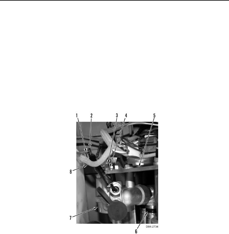
1. If not arctic kit heater equipped, disconnect chassis harness (Figure 3, Item 8) from oil filter bypass switch
(Figure 3, Item 1). Position chassis harness aside.
2. Using hydraulic line remover tool, disconnect two hydraulic hoses (Figure 3, Item 6) from filter base (Figure 3,
Item 7).
3. If not arctic kit heater equipped, remove three bolts (Figure 3, Item 3), washers (Figure 3, Item 4), one clip
(Figure 3, Item 2), and filter base (Figure 3, Item 7) from hydraulic system filter base bracket (Figure 3, Item 5).
Figure 3. Filter Base, Hoses, and Retaining Hardware.
0166