
TM 5-2410-240-23-2
0166
RIGHT DRIVE LOOP FILTER INSTALLATION CONTINUED
N OT E
Install tiedown strap as noted during removal.
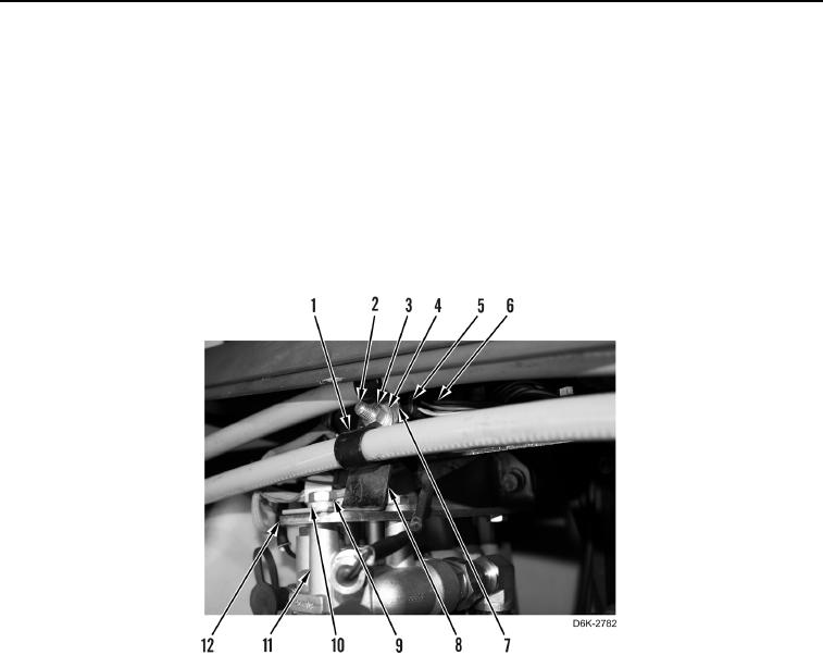
20. If arctic kit heater equipped, install filter base (Figure 9, Item 11), bracket (Figure 9, Item 8), three washers
(Figure 9, Item 10) and bolts (Figure 9, Item 9) on hydraulic system filter base bracket (Figure 9, Item 12).
21. If arctic kit heater equipped, install clip (Figure 9, Item 7), bolt (Figure 9, Item 2), two clamps (Figure 9, Item 1),
washers (Figure 9, Item 4) and nut (Figure 9, Item 3) on bracket (Figure 9, Item 8).
22. If arctic kit heater equipped, connect oil filter bypass switch (Figure 9, Item 6) from chassis harness and install
new tiedown strap (Figure 9, Item 5).
Figure 9. Base and Attaching Hardware Arctic Kit Heater Equipped.
0166