
TM 5-2410-240-23-2
0166
LEFT DRIVE LOOP FILTER AND WINCH FILTER INSTALLATION
000166
N OT E
This procedure covers installation of filter base for left drive loop filter. Follow the same
procedure when installing filter base for winch filter.
Install oil filter bypass switch, pressure tap, and fittings as noted during removal.
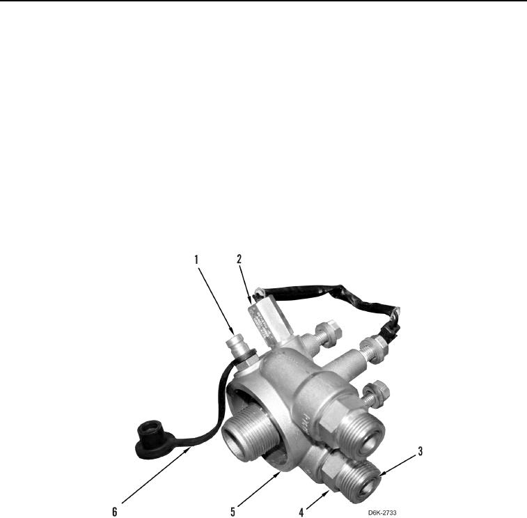
1. Lubricate seven new O-rings (Figure 11, Item 3) with lubricating oil.
2. Install four new O-rings (Figure 11, Item 3) on two fittings (Figure 11, Item 4).
3. Install two fittings (Figure 11, Item 4) on filter base (Figure 11, Item 5).
4. Install new O-ring (Figure 11, Item 3) on pressure tap (Figure 11, Item 1).
5. Install pressure tap (Figure 11, Item 1) on filter base (Figure 11, Item 5).
6. Install cap (Figure 11, Item 6) on pressure tap (Figure 11, Item 1).
7. Install two new O-rings (Figure 11, Item 3) on oil filter bypass switch (Figure 11, Item 2).
8. Install oil filter bypass switch (Figure 11, Item 2) on filter base (Figure 11, Item 5).
Figure 11. Filter Base, Oil Filter Bypass Switch, Pressure Tap, Cap, Fittings and O-rings.
0166