TM 5-2410-240-23-2
0167
INSTALLATION
000167
N OT E
The following procedure will remove one hydraulic filter bypass switch. Follow the same
procedure for each additional hydraulic filter bypass switch.
Install connectors as noted during removal.
1. Install new O-ring (Figure 3, Item 5) on hydraulic filter bypass switch (Figure 3, Item 4).
2. Install hydraulic filter bypass switch (Figure 3, Item 4) on filter base (Figure 3, Item 6).
3. Connect harness connector (Figure 3, Item 1) to sensor connector (Figure 3, Item 3).
4. Install new tiedown strap (Figure 3, Item 2) on sensor connector (Figure 3, Item 3).
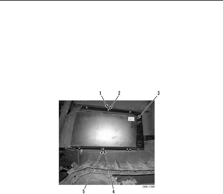
5. Install cover (Figure 3, Item 3), three washers (Figure 3, Item 2), nuts (Figure 3, Item 1), washers (Figure 3
Item 4), and bolts (Figure 3, Item 5) on machine.
Figure 3. Cover.
0167
END OF TASK
FOLLOW-ON TASKS
000167
Verify correct operation of machine (TM 5-2410-240-10).
END OF TASK
END OF WORK PACKAGE

