
TM 5-2410-240-23-2
0167
REMOVAL CONTINUED
N OT E
The following procedure will remove one hydraulic filter bypass switch. Follow the same
procedure for each additional hydraulic filter bypass switch.
Tag and mark connectors to aid installation.
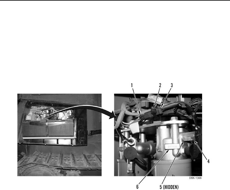
2. Remove tiedown strap (Figure 2, Item 2) from sensor connector (Figure 2, Item 3). Discard tiedown strap.
3. Disconnect harness connector (Figure 2, Item 1) from sensor connector (Figure 2, Item 3).
4. Remove hydraulic filter bypass switch (Figure 2, Item 4) from filter base (Figure 2, Item 6).
5. Remove O-ring (Figure 2, Item 5) from hydraulic filter bypass switch (Figure 2, Item 4). Discard O-ring.
Figure 2. Hydraulic Filter Bypass Switch.
0167
END OF TASK
CLEANING AND INSPECTION
000167
Clean and inspect all components IAW Mechanical General Maintenance Instructions (WP 0282).
END OF TASK