
TM 5-2410-240-23-2
0166
LEFT DRIVE LOOP FILTER AND WINCH FILTER INSTALLATION CONTINUED
N OT E
Remove caps or plugs from hydraulic tubes and fittings.
Install tubes, electrical connectors, tiedown strap, and clip as noted during removal.
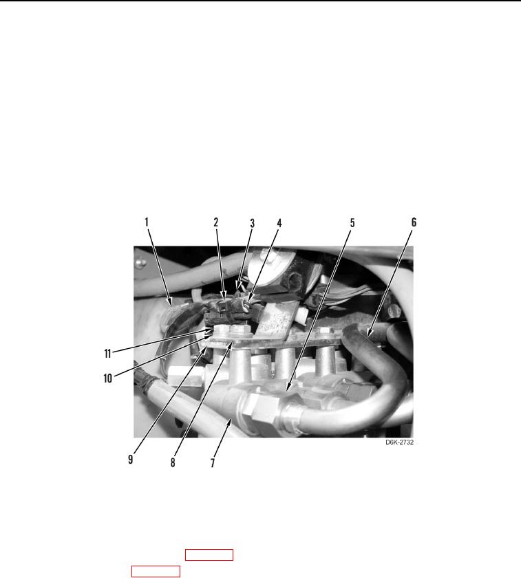
9. Loosely connect two tubes (Figure 12, Item 6) to filter base (Figure 12, Item 7).
10. Install filter base (Figure 12, Item 7), clip (Figure 12, Item 3), bracket (Figure 12, Item 8), three washers
(Figure 12, Item 10), and bolts (Figure 12, Item 11) on hydraulic system filter base bracket (Figure 12, Item 9).
11. Tighten two tube nuts (Figure 12, Item 5).
12. Connect oil filter bypass switch (Figure 12, Item 4) to chassis harness (Figure 12, Item 1).
13. Install new tiedown strap (Figure 12, Item 2) on chassis harness (Figure 12, Item 1) and clip (Figure 12,
Item 3).
Figure 12. Filter Base and Retaining Hardware.
0166
END OF TASK
FOLLOW-ON TASKS
000166
1. Install new hydraulic system filter(s) (WP 0164).
2. Check hydraulic oil level (WP 0160).
3. Verify correct operation of machine (TM 5-2410-240-10).
END OF TASK
END OF WORK PACKAGE
0166-15/(16 blank)