
TM 5-2410-240-23-2
0168
REMOVAL CONTINUED
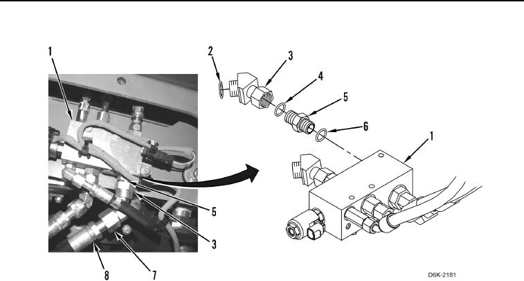
Figure 5. Demand Fan Hose.
0168
END OF TASK
CLEANING AND INSPECTION
000168
Clean and inspect all parts IAW Mechanical General Maintenance Instructions (WP 0282).
END OF TASK
INSTALLATION
000168
N OT E
Hydraulic hoses, fittings, and clamps are all installed using the same general method. This
procedure covers installation of one hydraulic hose assembly on machine.
Install hoses and fittings as noted during removal.
1. Install new O-ring (Figure 5, Item 6), connector (Figure 5, Item 5), new O-ring (Figure 5, Item 4), fitting
(Figure 5, Item 3), and new O-ring (Figure 5, Item 2) on demand fan manifold (Figure 5, Item 1).
2. Position hose (Figure 5, Item 8) on machine and connect hose fitting (Figure 5, Item 7) to demand fan manifold
(Figure 5, Item 1).