
TM 5-2410-240-23-2
0168
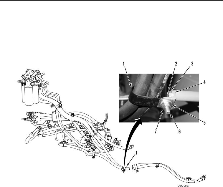
REMOVAL CONTINUED
N OT E
Note location of clamps to aid installation.
9. Remove nut (Figure 4, Item 7), washer (Figure 4, Item 5), bolt (Figure 4, Item 6), and clamp (Figure 4, Item 1)
from machine.
10. Remove bolt (Figure 4, Item 2), washer (Figure 4, Item 3), and bracket (Figure 4, Item 4) from machine.
Figure 4. Demand Fan Hose Clamp.
0168
N OT E
Note routing of hose to aid installation.
Note position of fitting to aid installation.
11. Loosen hose fitting (Figure 5, Item 7) and remove hose (Figure 5, Item 8) from machine.
12. Remove O-ring (Figure 5, Item 2) from fitting (Figure 5, Item 3). Discard O-ring.
13. Remove fitting (Figure 5, Item 3), O-ring (Figure 5, Item 4), connector (Figure 5, Item 5), and O-ring (Figure 5,
Item 6) from demand fan manifold (Figure 5, Item 1). Discard O-rings.