
TM 5-2410-240-23-2
0170
HOSES REMOVAL CONTINUED
N OT E
Note routing of hose to aid installation.
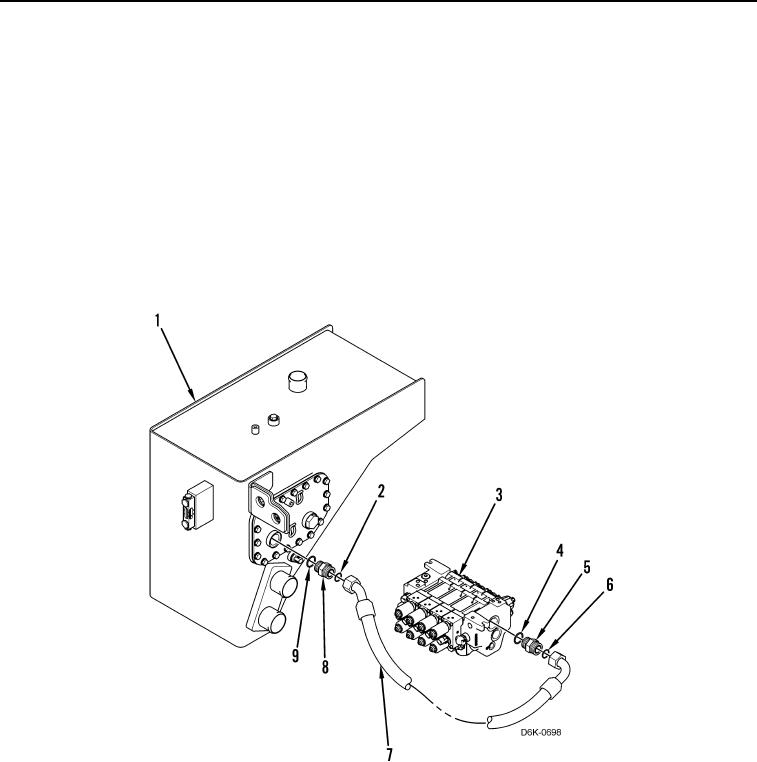
2. Disconnect hose (Figure 2, Item 7) and remove O-ring (Figure 2, Item 2) from hydraulic tank (Figure 2, Item 1).
Discard O-ring.
3. Remove check valve (Figure 2, item 8) and O-ring (Figure 2, Item 9) from hydraulic tank (Figure 2, Item 1).
Discard O-ring.
4. Disconnect hose (Figure 2, Item 7) and remove O-ring (Figure 2, Item 6) from valve bank (Figure 2, Item 3) and
remove hose from machine. Discard O-ring.
5. Remove connector (Figure 2, Item 5) and O-ring (Figure 2, Item 4) from valve bank (Figure 2, Item 3). Discard
O-ring.
Figure 2. Tank to Valve Bank Hose.
0170