
TM 5-2410-240-23-2
0170
HOSES REMOVAL CONTINUED
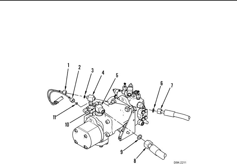
8. Disconnect two diagnostic tubes (Figure 4, Items 1 and 2) and remove two O-rings (Figure 4, Items 3 and 11)
from adapter (Figure 4, Item 10) and tee fitting (Figure 4, Item 4). Position diagnostic tubes aside and discard
O-rings.
9. Disconnect two hoses (Figure 4, Items 7 and 8) and remove two O-rings (Figure 4, Items 6 and 9) from two tee
fittings (Figure 4, Items 4 and 5). Discard O-rings.
10. Remove two hoses (Figure 4, Items 7 and 8) from machine.
Figure 4. Pump Hoses.
0170