
TM 5-2410-240-23-2
0170
DIAGNOSTIC TUBES REMOVAL
000170
N OT E
Diagnostic hoses and fittings from the test panel to the pump are all removed using the
same general method. This procedure covers removal of one hydraulic hose assembly
from machine.
Tag all hoses, tubes, and fittings to aid installation.
Note routing of hoses to aid installation.
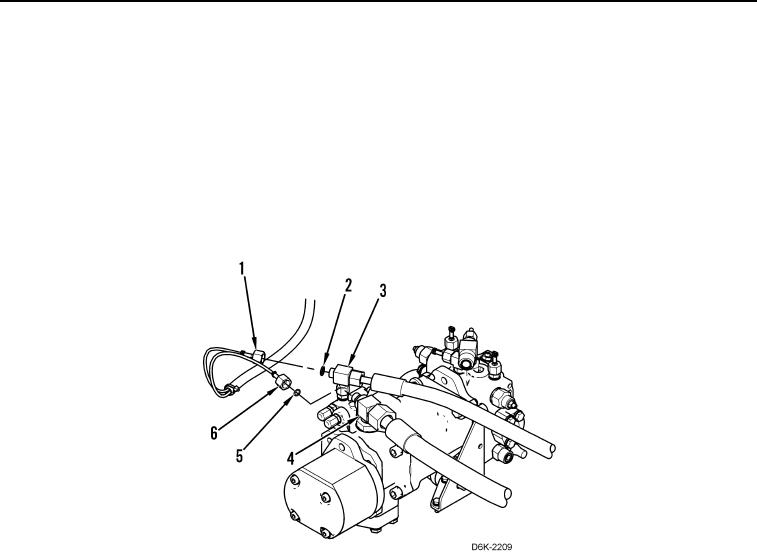
1. Disconnect two diagnostic tube nuts (Figure 8, Items 1 and 6) from two fittings (Figure 8, Items 3 and 4), and
remove two O-rings (Figure 8, Items 2 and 5) from two fittings (Figure 8, Items 3 and 4). Discard O-rings.
Figure 8. Diagnostic Tubes.
0170