
TM 5-2410-240-23-2
0170
DIAGNOSTIC TUBES INSTALLATION
000170
N OT E
Diagnostic tubes and fittings from the test panel to the pump are all installed using the
same general method. This procedure covers installation of one hydraulic hose assembly
on machine.
Install all hoses, tubes, and fittings as noted during removal.
1. Install two diagnostic tubes (Figure 10, Item 7) in conduit (Figure 10, Item 6) and install diagnostic tubes on
machine.
2. Install five new tiedown straps (Figure 10, Item 5) on diagnostic hoses (Figure 10, Item 7).
3. Install four clamps (Figure 10, Item 2), four washers (Figure 10, Item 3), three bolts (Figure 10, Item 4), and nut
(Figure 10, Item 1) on machine.
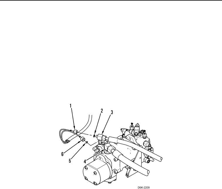
4. Install two new O-rings (Figure 11, Items 2 and 5) on two fittings (Figure 11, Items 3 and 4) and connect two
diagnostic tube nuts (Figure 11, Items 1 and 6) to two fittings (Figure 11, Items 3 and 4).
Figure 11. Diagnostic Tubes.
0170