
TM 5-2410-240-23-2
0170
HOSES INSTALLATION CONTINUED
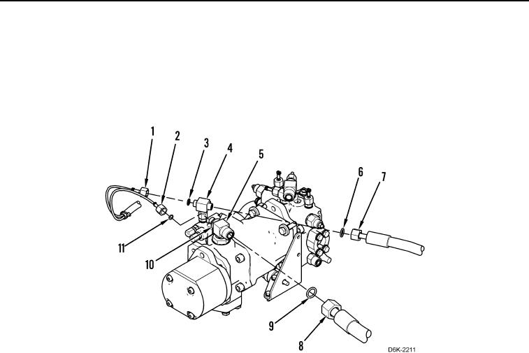
11. Remove caps and position two hoses (Figure 16, Items 7 and 8) on machine.
12. Install two new O-rings (Figure 16, Items 6 and 9) on two tee fittings (Figure 16, Items 4 and 5), and connect
two hoses (Figure 16, Items 7 and 8) to two tee fittings (Figure 16, Items 4 and 5).
13. Install two new O-rings (Figure 16, Items 3 and 11) and connect two diagnostic tubes (Figure 16, Items 1 and
2) to adapter (Figure 16, Item 10) and tee fitting (Figure 16, Item 4).
Figure 16. Pump Hoses.
0170