
TM 5-2410-240-23-2
0170
HOSES INSTALLATION CONTINUED
N OT E
Install hoses and fittings as noted during removal.
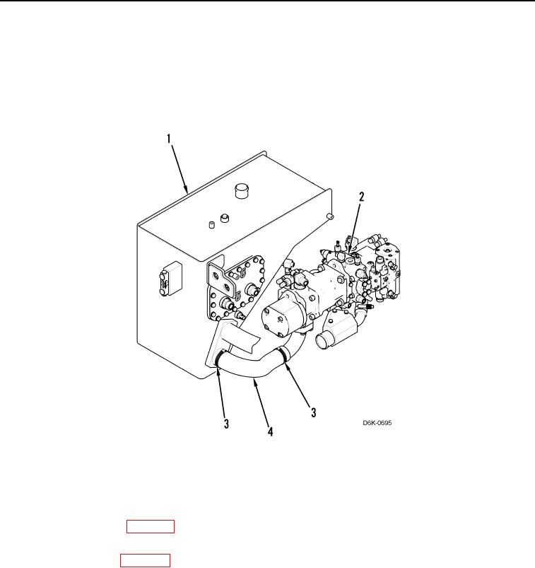
20. Connect hose (Figure 19, Item 4) to hydraulic tank (Figure 19, Item 1) and pump (Figure 19, Item 2), and
tighten clamps (Figure 19, Item 3).
Figure 19. Hydraulic Tank to Pump Hose.
0170
END OF TASK
FOLLOW-ON TASKS
000170
1. Fill with hydraulic fluid (WP 0160).
2. Install front cab floor plate (WP 0205).
3. Install bottom guards (WP 0156).
4. Verify correct operation of machine (TM 5-2410-240-10).
END OF TASK
END OF WORK PACKAGE
0170-21/(22 blank)