
TM 5-2410-240-23-2
0170
HOSES INSTALLATION CONTINUED
N OT E
Install hoses and fittings as noted during removal.
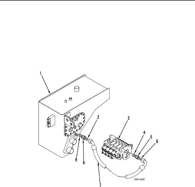
16. Install new O-ring (Figure 18, Item 4) and connector (Figure 18, Item 5) on valve bank (Figure 18, Item 3).
17. Install new O-ring (Figure 18, Item 6) on connector (Figure 18, Item 5), and connect hose (Figure 18, Item 7) to
valve bank (Figure 18, Item 3).
18. Install new O-ring (Figure 18, Item 9), check valve (Figure 18, Item 8), and new O-ring (Figure 18, Item 2) on
hydraulic tank (Figure 18, Item 1).
19. Remove caps and connect hose (Figure 18, Item 7) to hydraulic tank (Figure 18, Item 1).
Figure 18. Tank to Valve Bank Hose.
0170