
TM 5-2410-240-23-2
0170
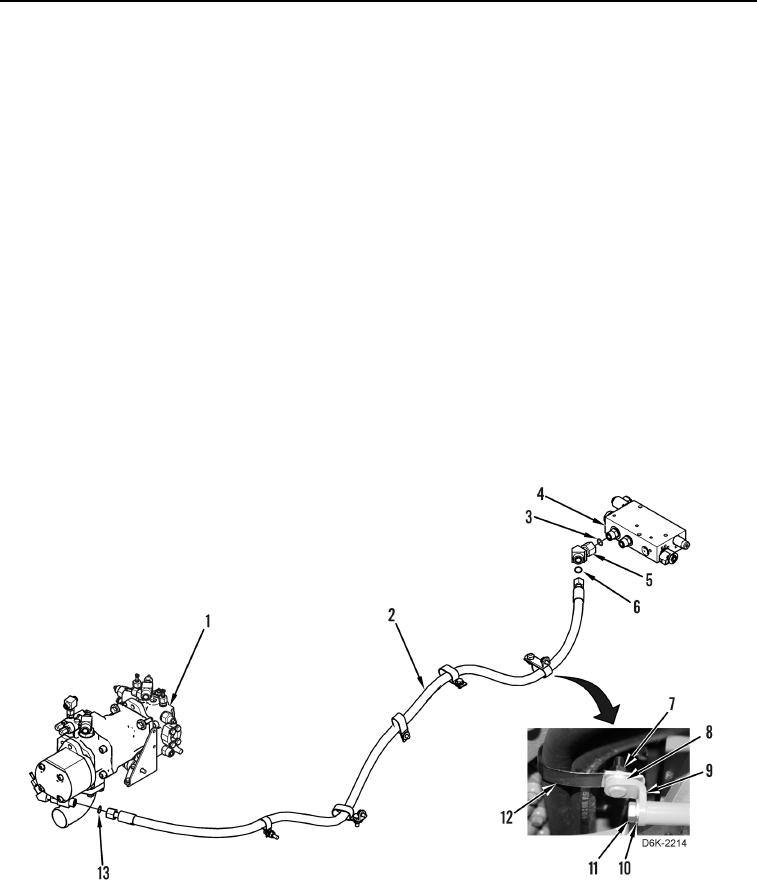
HOSES INSTALLATION
000170
N OT E
Hydraulic hoses, fittings, and clamps are all installed using the same general method. This
procedure covers installation of one hydraulic hose assembly on machine.
Install hoses and clamps as noted during removal.
1. Remove caps and install new O-ring (Figure 13, Item 6) on elbow (Figure 13, Item 5).
2. Install elbow (Figure 13, Item 5) and new O-ring (Figure 13, Item 3) on demand fan manifold (Figure 13,
Item 4).
3. Position hose (Figure 13, Item 2) on machine and connect hose (Figure 13, Item 2) to elbow (Figure 13,
Item 5).
N OT E
Hose clamps are all installed using the same general method. This procedure covers
installation of one clamp on machine.
Install clamps as noted during removal.
4. Install bracket (Figure 13, Item 9), washer (Figure 13, Item 10), and bolt (Figure 13, Item 11) on machine.
5. Install spacer (Figure 13, Item 8), clamp (Figure 13, Item 12), and nut (Figure 13, Item 7) on machine.
6. Remove caps, install new O-ring (Figure 13, Item 13), and connect hose (Figure 13, Item 2) to pump
(Figure 13, Item 1).
Figure 13. Pump to Demand Fan Manifold.
0170