
TM 5-2410-240-23-2
0170
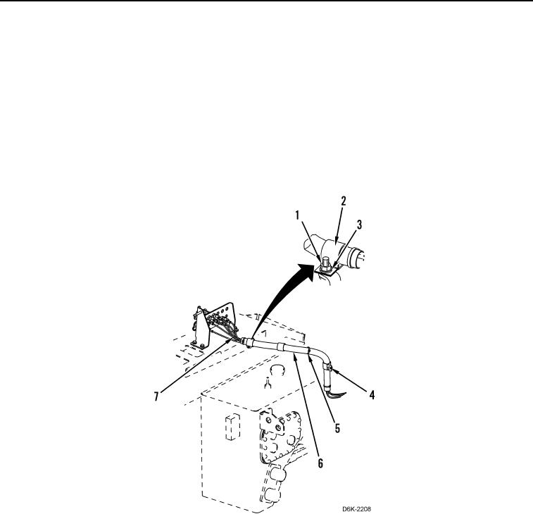
DIAGNOSTIC TUBES REMOVAL CONTINUED
4. Remove nut (Figure 10, Item 1), three bolts (Figure 10, Item 4), four washers (Figure 10, Item 3), and four
clamps (Figure 10, Item 2) from machine.
N OT E
Note position of tiedown straps for installation.
5. Remove five tiedown straps (Figure 10, Item 5) from diagnostic tubes (Figure 10, Item 7). Discard tiedown
straps.
6. Remove diagnostic tubes (Figure 10, Item 7) from conduit (Figure 10, Item 6).
7. Remove diagnostic tubes (Figure 10, Item 7) from machine.
Figure 10. Diagnostic Tube Conduit.
0170
END OF TASK
CLEANING AND INSPECTION
000170
Clean and inspect all parts IAW Mechanical General Maintenance Instructions (WP 0282).
END OF TASK