
TM 5-2410-240-23-2
0170
DIAGNOSTIC TUBES REMOVAL CONTINUED
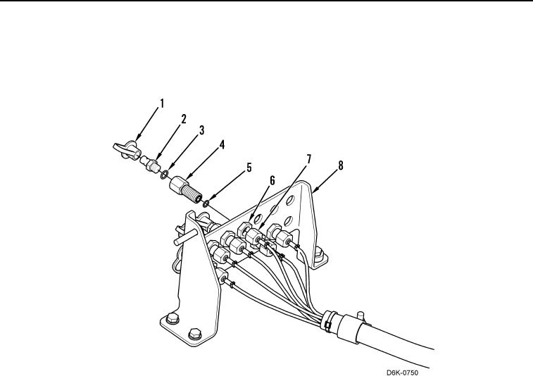
2. Disconnect diagnostic tube nut (Figure 9, Item 7) from fitting (Figure 9, Item 4) and position aside.
3. Remove dust cap (Figure 9, Item 1), connector (Figure 9, Item 2), O-ring (Figure 9, Item 3), fitting (Figure 9,
Item 4), O-ring (Figure 9, Item 5), and nut (Figure 9, Item 6) from test panel (Figure 9, Item 8). Discard O-rings.
Figure 9. Test Panel and Hoses.
0170