• Home
  • Download PDF
  • Order CD-ROM
  • Order in Print
Figure 11. Diagnostic Tubes.
Figure 13. Pump to Demand Fan Manifold.

Field Maintenance Manual 2 D6K Dozer Type I With Winch and Type II With Ripper
Page Navigation
  1231    1232    1233    1234    1235  1236  1237    1238    1239    1240    1241  
img
.
TM 5-2410-240-23-2
0170
DIAGNOSTIC TUBES INSTALLATION CONTINUED
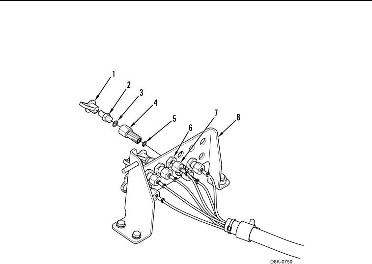
5. Install new O-ring (Figure 12, Item 5), fitting (Figure 12, Item 4), nut (Figure 12, Item 6), new O-ring (Figure 12,
Item 3), connector (Figure 12, Item 2), and dust cap (Figure 12, Item 1) on test panel (Figure 12, Item 8).
6. Connect tube nut (Figure 12, Item 7) to fitting (Figure 12, Item 4).
.
Figure 12. Test Panel and Hoses.
0170
END OF TASK
0170-14


Privacy Statement
Press Release
Contact

© Copyright Integrated Publishing, Inc.. All Rights Reserved.