
TM 5-2410-240-23-2
0170
HOSES REMOVAL CONTINUED
N OT E
Note routing of hoses and fittings to aid installation.
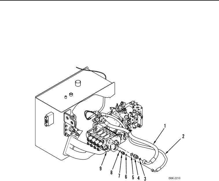
6. Disconnect two hoses (Figure 3, Items 1 and 2) and remove two O-rings (Figure 3, Items 3 and 6) from two
connectors (Figure 3, Items 4 and 7). Discard O-rings.
7. Remove two connectors (Figure 3, Items 4 and 7) and O-rings (Figure 3, Items 5 and 8) from valve bank
(Figure 3, Item 9). Discard O-rings.
Figure 3. Valve Bank Hoses.
0170