
TM 5-2410-240-23-2
0173
INSTALLATION CONTINUED
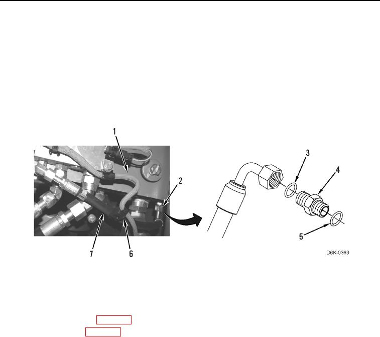
20. Install new O-ring (Figure 14, Item 5) and connector (Figure 14, Item 4) on demand fan manifold (Figure 14,
Item 1).
21. Install new O-ring (Figure 14, Item 3) on connector (Figure 14, Item 4) and tighten hose fitting (Figure 14,
Item 2) on connector (Figure 14, Item 4).
N OT E
Install tiedown strap as noted during removal.
22. Install new tiedown strap (Figure 14, Item 6) on hose (Figure 14, Item 7).
Figure 14. Hose Connector.
0173
END OF TASK
FOLLOW-ON TASKS
000173
1. Check hydraulic oil level (WP 0160).
2. Install bottom guards (WP 0156).
3. Verify correct operation of machine (TM 5-2410-240-10).
END OF TASK
END OF WORK PACKAGE
0173-13/(14 blank)