
TM 5-2410-240-23-2
0173
INSTALLATION
000173
WARN I N G
Lubricating/hydraulic oils used in performance of maintenance can be very slippery.
Immediately wipe up any spills. Failure to follow this warning may result in injury to
personnel.
N OT E
Hydraulic hoses, fittings, and clamps are all installed using the same general method. This
procedure covers removal of one hydraulic hose assembly from machine.
Install hoses as noted during removal.
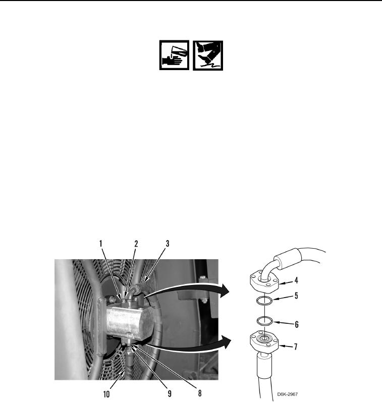
1. Remove caps and install new O-ring (Figure 8, Item 6) on hose (Figure 8, Item 10).
2. Install hose (Figure 8, Item 10), flange (Figure 8, Item 7), four washers (Figure 8, Item 8), and bolts (Figure 8,
Item 9) on machine.
3. Remove caps and install new O-ring (Figure 8, Item 5) on hose (Figure 8, Item 3).
4. Install hose (Figure 8, Item 3), flange (Figure 8, Item 4), four washers (Figure 8, Item 1), and bolts (Figure 8,
Item 2) on machine.
Figure 8. Hoses.
0173