
TM 5-2410-240-23-2
0173
REMOVAL CONTINUED
N OT E
Tag all hoses and fittings to aid installation.
Use a container to catch any fluid that may drain from hoses or system. Dispose of fluid
IAW local policy and ordinances. Ensure all spills are cleaned up.
Note routing of hoses and lines to aid installation.
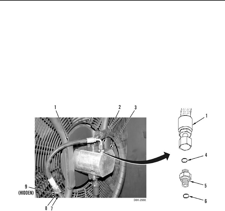
12. Loosen hose fitting (Figure 6, Item 8) from hose (Figure 6, Item 1), remove O-ring (Figure 6, Item 9) from hose,
and remove hose (Figure 6, Item 7) from machine. Discard O-ring.
13. Loosen hose fitting (Figure 6, Item 2) from connector (Figure 6, Item 5) and remove hose (Figure 6, Item 1)
from machine.
14. Remove O-ring (Figure 6, Item 4) from connector (Figure 6, Item 5). Discard O-ring.
15. Remove connector (Figure 6, Item 5) and O-ring (Figure 6, Item 6) from motor (Figure 6, Item 3). Discard
O-ring.
Figure 6. Hydraulic Fan and Hose.
0173