
TM 5-2410-240-23-2
0173
INSTALLATION CONTINUED
N OT E
Hydraulic hoses, fittings, and clamps are all installed using the same general method. This
procedure covers installation of one hydraulic hose assembly on machine.
Install hoses as noted during removal.
12. Close lower radiator grill and upper radiator grill (TM 5-2410-240-10).
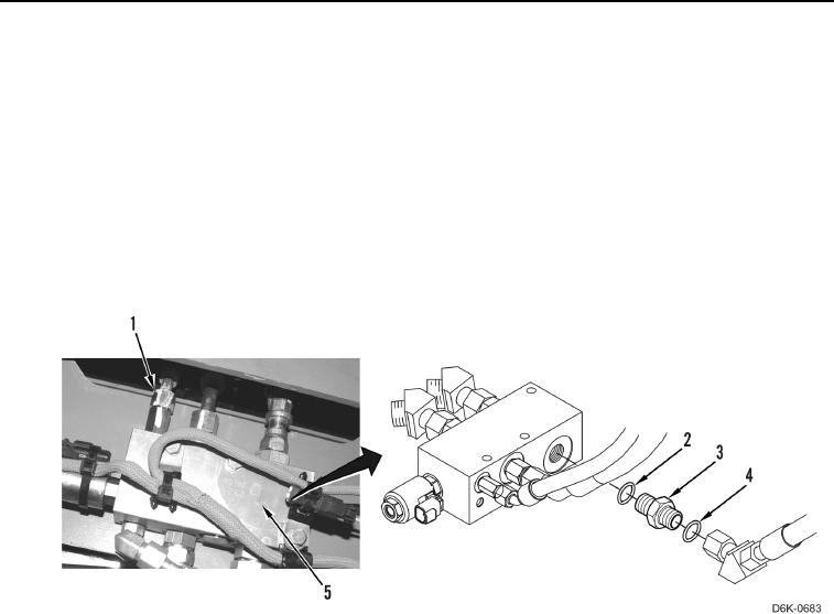
13. Install three new O-rings (Figure 12, Item 2) and connectors (Figure 12, Item 3) on demand fan manifold
(Figure 12, Item 5).
14. Install three new O-rings (Figure 12, Item 4) on three connectors (Figure 12, Item 3).
15. Tighten three hose fittings (Figure 12, Item 1) on demand fan manifold (Figure 12, Item 5).
Figure 12. Demand Fan Hoses.
0173