
TM 5-2410-240-23-3
0180
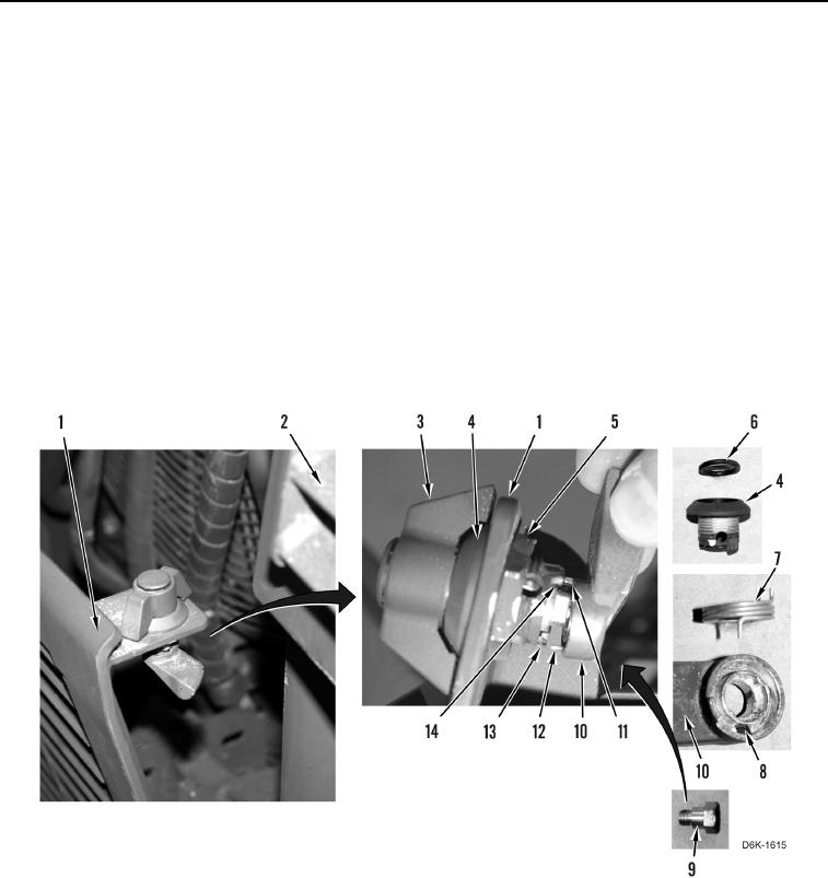
LOWER RADIATOR GRILL LATCH ASSEMBLY INSTALLATION
000180
N OT E
Install latch body, latch handle, and latch cam as noted during removal.
1. Install new O-ring (Figure 7, Item 6) on latch body (Figure 7, Item 4).
2. Install latch body (Figure 7, Item 4) on lower radiator grill (Figure 7, Item 1).
3. Install nut (Figure 7, Item 5) retaining latch body (Figure 7, Item 4) on lower radiator grill (Figure 7, Item 1).
4. Install latch handle (Figure 7, Item 3) on latch body (Figure 7, Item 4). Position latch handle as shown.
5. Install long end of spring (Figure 7, Item 7) in hole (Figure 7, Item 8) on latch cam (Figure 7, Item 10).
6. Position short end of spring (Figure 7, Item 12) on tab (Figure 7, Item 13).
7. Simultaneously turn latch cam (Figure 7, Item 10) and latch handle (Figure 7, Item 3) clockwise. When tab
(Figure 7, Item 11) passes boss (Figure 7, Item 14), seat latch cam on latch body (Figure 7, Item 4).
8. Install bolt (Figure 7, Item 9) retaining latch cam (Figure 7, Item 10) on latch body (Figure 7, Item 4).
9. Close lower radiator grill (TM 5-2410-240-10).
Figure 7. Latch Assembly and Lower Radiator Grill.
0180
10. Close and latch upper radiator grill (TM 5-2410-240-10).
END OF TASK