
TM 5-2410-240-23-3
0196
ASSEMBLY CONTINUED
Figure 30. Blade Angle Control Valve.
0196
N OT E
Install O-rings as noted during removal.
New solenoid comes with three O-rings already installed.
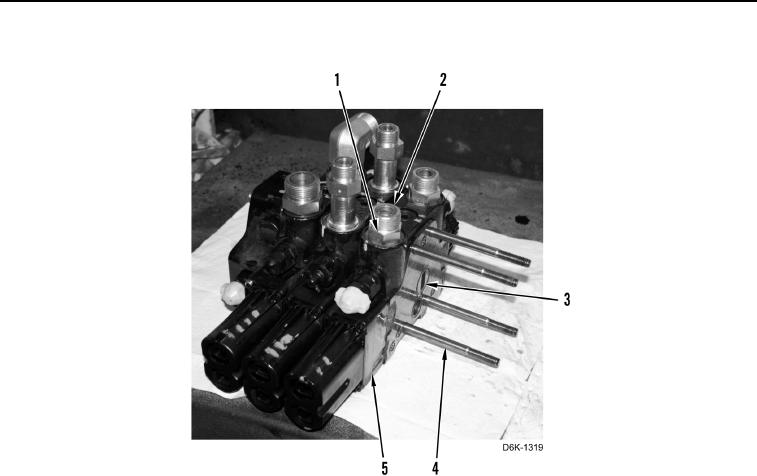
22. Ensure six new O-rings (Figure 31, Item 3) are installed on two solenoids (Figure 31, Item 2).
23. Install two solenoids (Figure 31, Item 2), clamps (Figure 31, Item 4), and bolts (Figure 31, Item 5) on ripper
control valve (Figure 31, Item 1).