
TM 5-2410-240-23-3
0196
ASSEMBLY CONTINUED
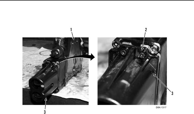
6. Install cover (Figure 23, Item 3) and three bolts (Figure 23, Item 2) on blade tilt control valve (Figure 23,
Item 1).
Figure 23. Valve Solenoid Cover.
0196
C AU T I O N
Install valves in correct order as noted during disassembly. Failure to follow this caution
may damage equipment.
N OT E
Install O-rings as noted during removal.
7. Install six new O-rings (Figure 24, Item 3) on blade lift control valve (Figure 24, Item 5).
8. Install two fittings (Figure 24, Item 1) and four new O-rings (Figure 24, Item 2) on blade lift control valve
(Figure 24, Item 5).
9. Install blade lift control valve (Figure 24, Item 5) on bolts (Figure 24, Item 4).