
TM 5-2410-240-23-3
0196
DISASSEMBLY CONTINUED
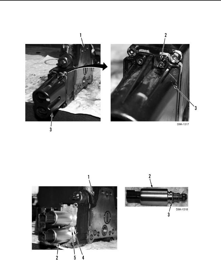
20. Remove three bolts (Figure 16, Item 2) and cover (Figure 16, Item 3) from blade tilt control valve
(Figure 16, Item 1).
Figure 16. Valve Solenoid Cover.
0196
21. Remove two bolts (Figure 17, Item 5), clamps (Figure 17, Item 4), and solenoids (Figure 17, Item 2) from blade
tilt control valve (Figure 17, Item 1).
22. Remove six O-rings (Figure 17, Item 3) from two solenoids (Figure 17, Item 2). Discard O-rings.
Figure 17. Solenoids.
0196