
TM 5-2410-240-23-3
0196
DISASSEMBLY CONTINUED
C AU T I O N
Mark each valve to identify its location to aid installation. Valves installed in the incorrect
order may cause damage to equipment.
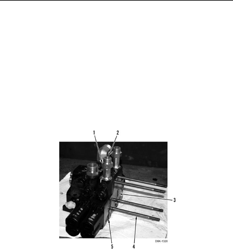
17. Remove blade tilt control valve (Figure 15, Item 5) from bolts (Figure 15, Item 4).
N OT E
Note location and size of O-rings to aid installation.
18. Remove two fittings (Figure 15, Item 1) and four O-rings (Figure 15, Item 2) from blade tilt control valve
(Figure 15, Item 5). Discard O-rings.
N OT E
During removal, O-rings may stick to either side of valve face.
Note location and size of O-rings to aid installation.
19. Remove six O-rings (Figure 15, Item 3) from blade tilt control valve (Figure 15, Item 5). Discard O-rings.
Figure 15. Blade Tilt Control Valve.
0196