
TM 5-2410-240-23-3
0196
DISASSEMBLY
000196
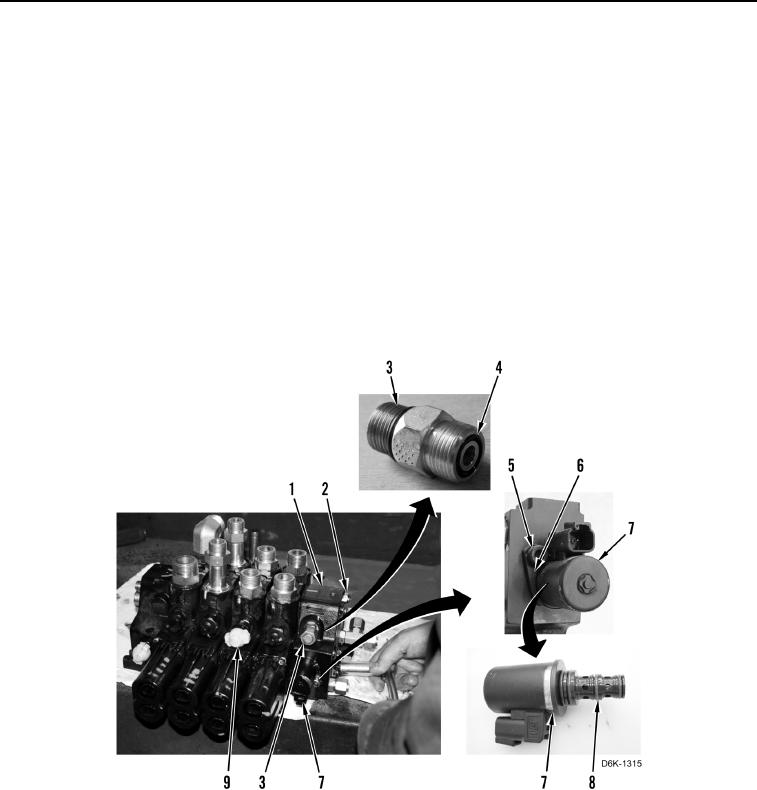
1. Remove four nuts (Figure 8, Item 2) and outlet manifold (Figure 8, Item 1) from valve bank (Figure 8, Item 9).
N OT E
Note location and position of fittings to aid installation.
2. Remove three fittings (Figure 8, Item 3) and seven O-rings (Figure 8, Item 4) from outlet manifold (Figure 8,
Item 1). Discard O-rings.
3. Remove bolt (Figure 8, Item 5), clamp (Figure 8, Item 6), and solenoid (Figure 8, Item 7) from outlet manifold
(Figure 8, Item 1).
N OT E
Note location and size of O-rings to aid installation.
4. Remove three O-rings (Figure 8, Item 8) from solenoid (Figure 8, Item 7). Discard O-rings.
Figure 8. Outlet Manifold.
0196