
TM 5-2410-240-23-3
0196
REMOVAL CONTINUED
WARN I N G
Hydraulic oil is very slippery. Immediately wipe up any spills. Failure to follow this warning
may result in injury to personnel.
N OT E
Cap all open ports to avoid contamination.
Tag and note position and routing of all hoses and lines to aid installation.
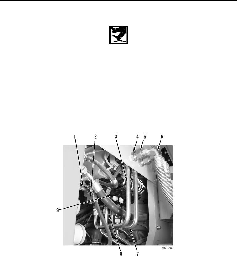
6. Disconnect seven hoses (Figure 4, Item 1) from valve bank (Figure 4, Item 2). Position hoses aside.
7. Loosen two tube nuts (Figure 4, Item 8) and remove two lines (Figure 4, Item 7) from ripper valve assembly
(Figure 4, Item 9).
8. Loosen two tube nuts (Figure 4, Item 5) and remove two hoses (Figure 4, Item 6) from machine. Position
hoses aside.
9. Remove two nuts (Figure 4, Item 4) and remove two lines (Figure 4, Item 3) from machine.
Figure 4. Outlet Manifold Hoses.
0196