• Home
  • Download PDF
  • Order CD-ROM
  • Order in Print
Figure 4. Outlet Manifold Hoses.
Figure 6. Valve Bank Lines.

Field Maintenance Manual 3 D6K Dozer Type I With Winch and Type II With Ripper
Page Navigation
  189    190    191    192    193  194  195    196    197    198    199  
img
.
TM 5-2410-240-23-3
0196
REMOVAL CONTINUED
N OT E
Tag and mark all electrical connectors to aid installation.
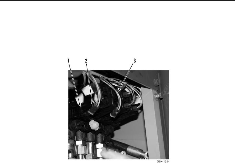
10. Disconnect nine connectors (Figure 5, Item 2) from valve bank (Figure 5, Item 1). Position nine harnesses
(Figure 5, Item 3) aside.
Figure 5. Electrical Connectors.
0196
0196-4


Privacy Statement
Press Release
Contact

© Copyright Integrated Publishing, Inc.. All Rights Reserved.