
TM 5-2410-240-23-3
0196
REMOVAL CONTINUED
2. Remove eight bolts (Figure 2, Item 2), washers (Figure 2, Item 1), plate (Figure 2, Item 3,) and plate (Figure 2,
Item 4) from machine.
Figure 2. Rear Top Plates.
0196
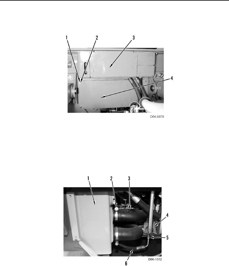
3. Loosen four clamps (Figure 3, Item 2) and remove two hoses (Figure 3, Item 3) from machine
(Figure 3, Item 1).
4. Remove four clamps (Figure 3, Item 2) from two hoses (Figure 3, Item 3).
5. Loosen tube nut (Figure 3, Item 5) and remove hose (Figure 3, Item 6) from drive motor (Figure 3, Item 4).
Place hose aside.
Figure 3. Hydraulic Tank Supply Hoses.
0196