
TM 5-2410-240-23-3
0195
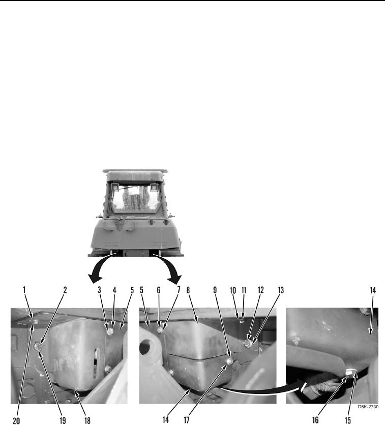
ACCESS COVERS INSTALLATION CONTINUED
2. Install upper right access cover (Figure 13, Item 8), spacer (Figure 13, Item 13), and bolt (Figure 13, Item 12)
on machine.
3. Install washer (Figure 13, Item 11) and bolt (Figure 13, Item 10) on upper right access cover (Figure 13,
Item 8).
4. Install left access cover (Figure 13, Item 18), spacer (Figure 13, Item 19), and bolt (Figure 13, Item 2) on
machine.
5. Install washer (Figure 13, Item 1) and bolt (Figure 13, Item 20) on left access cover (Figure 13, Item 18).
6. With assistance, install center access cover (Figure 13, Item 5), three washers (Figure 13, Items 3 and 7), and
bolts (Figure 13, Items 4 and 6) on machine.
7. Install lower right access cover (Figure 13, Item 14), two washers (Figure 13, Item 17), and bolts (Figure 13,
Item 9) on machine.
8. Install washer (Figure 13, Item 15) and bolt (Figure 13, Item 16) on lower access cover (Figure 13, Item 14).
Figure 13. Left, Center, Upper, and Lower Access Covers and Retaining Hardware on Rear of Machine.
0195