
TM 5-2410-240-23-3
0196
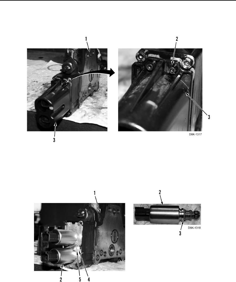
DISASSEMBLY CONTINUED
8. Remove three bolts (Figure 10, Item 2) and cover (Figure 10, Item 3) from ripper control valve (Figure 10,
Item 1).
Figure 10. Valve Solenoid Cover.
0196
9. Remove two bolts (Figure 11, Item 5), clamps (Figure 11, Item 4), and solenoids (Figure 11, Item 2) from ripper
control valve (Figure 10, Item 1).
10. Remove six O-rings (Figure 11, Item 3) from two solenoids (Figure 11, Item 2). Discard O-rings.
Figure 11. Solenoids.
0196