
TM 5-2410-240-23-3
0196
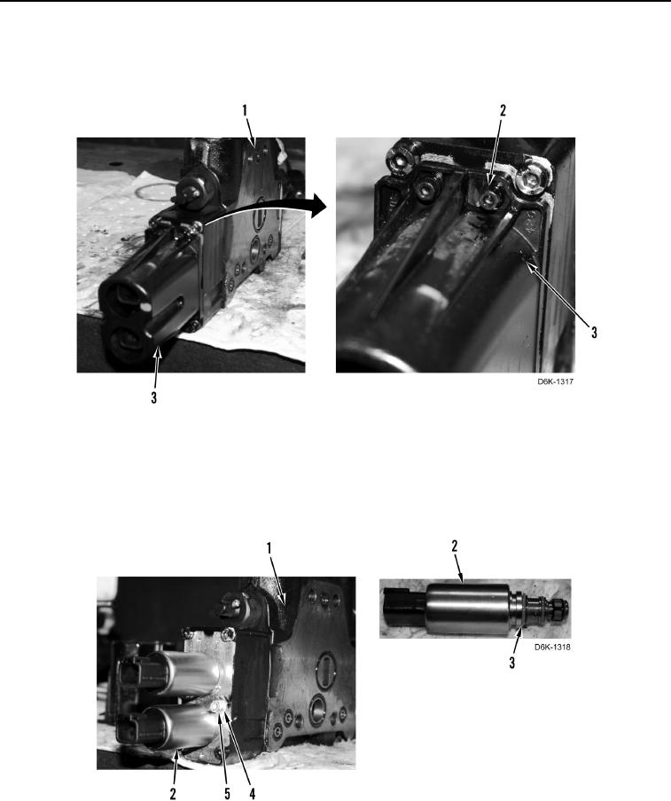
DISASSEMBLY CONTINUED
26. Remove three bolts (Figure 19, Item 2) and cover (Figure 19, Item 3) from blade lift control valve
(Figure 19, Item 1).
Figure 19. Valve Solenoid Cover.
0196
27. Remove two bolts (Figure 20, Item 5), clamps (Figure 20, Item 4), and solenoids (Figure 20, Item 2) from blade
lift control valve (Figure 20, Item 1).
28. Remove six O-rings (Figure 20, Item 3) from two solenoids (Figure 20, Item 2). Discard O-rings.
Figure 20. Solenoids.
0196