
TM 5-2410-240-23-3
0196
ASSEMBLY CONTINUED
N OT E
Install O-rings as noted during removal.
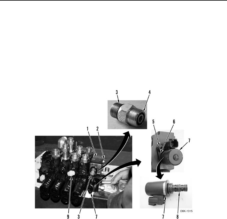
New solenoid comes with three O-rings already installed.
28. Ensure three new O-rings (Figure 34, Item 8) are installed on solenoid (Figure 34, Item 7).
29. Install solenoid (Figure 34, Item 7), clamp (Figure 34, Item 6), and bolt (Figure 34, Item 5) on outlet manifold
(Figure 34, Item 1).
30. Install seven new O-rings (Figure 34, Item 4) and three fittings (Figure 34, Item 3) on outlet manifold
(Figure 34, Item 1).
31. Install outlet manifold (Figure 34, Item 1) and four nuts (Figure 34, Item 2) on valve bank (Figure 34, Item 9).
Figure 34. Outlet Manifold.
0196
END OF TASK