
TM 5-2410-240-23-3
0196
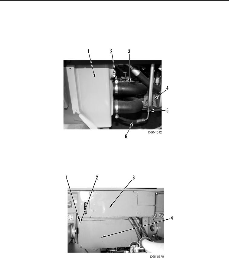
INSTALLATION CONTINUED
9. Install hose (Figure 39, Item 6) and tube nut (Figure 39, Item 5) on drive motor (Figure 39, Item 4).
10. Install four clamps (Figure 39, Item 2) on two hoses (Figure 39, Item 3).
11. Install two hoses (Figure 39, Item 3) on machine (Figure 39, Item 1) and tighten four clamps
(Figure 39, Item 2).
Figure 39. Hydraulic Tank Supply Hoses.
0196
12. Install plate (Figure 40, Item 4), plate (Figure 40, Item 3), eight washers (Figure 40, Item 1), and bolts
(Figure 40, Item 2) on machine.
Figure 40. Rear Top Plates.
0196