• Home
  • Download PDF
  • Order CD-ROM
  • Order in Print
Figure 36. Valve Bank Lines.
Figure 38. Outlet Manifold Hoses.

Field Maintenance Manual 3 D6K Dozer Type I With Winch and Type II With Ripper
Page Navigation
  215    216    217    218    219  220  221    222    223    224    225  
img
.
TM 5-2410-240-23-3
0196
INSTALLATION CONTINUED
N OT E
Install electrical connectors as noted during removal.
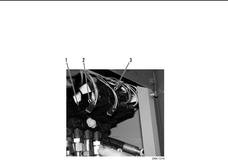
4. Position nine harnesses (Figure 37, Item 1) and connect nine connectors (Figure 37, Item 2) to valve bank
(Figure 37, Item 3).
Figure 37. Electrical Connectors.
0196
0196-30


Privacy Statement
Press Release
Contact

© Copyright Integrated Publishing, Inc.. All Rights Reserved.