
TM 5-2410-240-23-3
0196
INSTALLATION CONTINUED
WARN I N G
Hydraulic oil is very slippery. Immediately wipe up any spills. Failure to follow this warning
may result in injury to personnel.
N OT E
Remove caps from ports for installation.
Install hoses and lines as noted during removal.
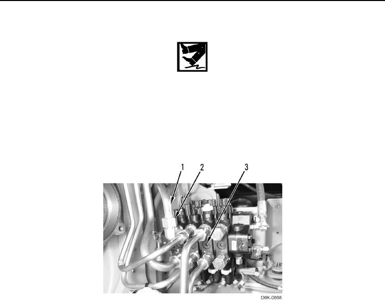
3. Install six lines (Figure 36, Item 1) and tube nuts (Figure 36, Item 2) on valve bank (Figure 36, Item 3).
Figure 36. Valve Bank Lines.
0196