
TM 5-2410-240-23-3
0218
REMOVAL
000218
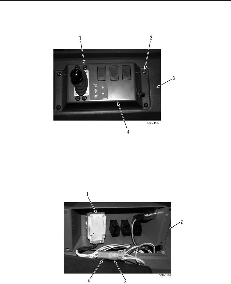
1. Remove eight screws (Figure 1, Items 1 and 2) and ripper control panel (Figure 1, Item 4) from console
(Figure 1, Item 3).
Figure 1. Ripper Operation Control Handle Panel.
0218
N OT E
Tag electrical connector to aid installation.
2. Disconnect ripper control harness connector (Figure 2, Item 4) from main harness connector (Figure 2, Item 3).
3. Remove ripper control lever (Figure 2, Item 1) from ripper control panel (Figure 2, Item 2).
Figure 2. Ripper Operation Control Handle Electrical Connector.
0218
END OF TASK