• Home
  • Download PDF
  • Order CD-ROM
  • Order in Print
Figure 3. Winch Control Handle Panel Components.
Figure 5. Winch Operation Electrical Connectors.

Field Maintenance Manual 3 D6K Dozer Type I With Winch and Type II With Ripper
Page Navigation
  392    393    394    395    396  397  398    399    400    401    402  
img
.
TM 5-2410-240-23-3
0217
INSTALLATION
000217
N OT E
Install electrical switches as tagged during removal.
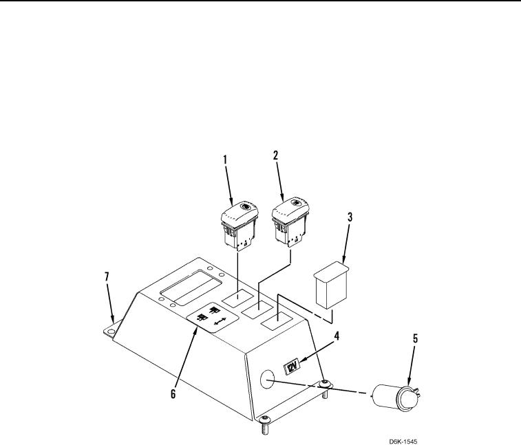
1. Install winch free-spool switch (Figure 4, Item 1), winch brake switch (Figure 4, Item 2), switch blank (Figure 4,
Item 3), 12V label (Figure 4, Item 4), 12V receptacle (Figure 4, Item 5), and control label (Figure 4, Item 6) on
winch control panel (Figure 4, Item 7).
Figure 4. Winch Control Handle Panel Components.
0217
0217-4


Privacy Statement
Press Release
Contact

© Copyright Integrated Publishing, Inc.. All Rights Reserved.