
TM 5-2410-240-23-3
0217
INSTALLATION CONTINUED
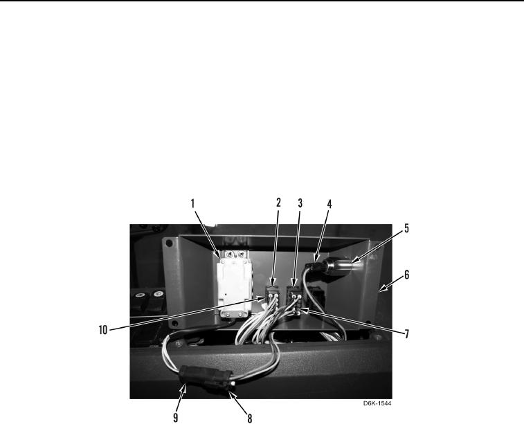
2. Install winch control lever (Figure 5, Item 1) on winch control panel (Figure 5, Item 6).
N OT E
Install electrical connectors as tagged during removal.
3. Connect 12V supply connector (Figure 5, Item 4) on 12V receptacle (Figure 5, Item 5).
4. Connect winch brake harness connector (Figure 5, Item 7) on winch brake switch (Figure 5, Item 3).
5. Connect winch free-spool harness connector (Figure 5, Item 10) on winch free-spool switch (Figure 5, Item 2).
6. Connect winch control harness connector (Figure 5, Item 8) on winch control lever connector
(Figure 5, Item 9).
Figure 5. Winch Operation Electrical Connectors.
0217