
TM 5-2410-240-23-3
0217
REMOVAL CONTINUED
N OT E
Tag electrical switches to aid installation.
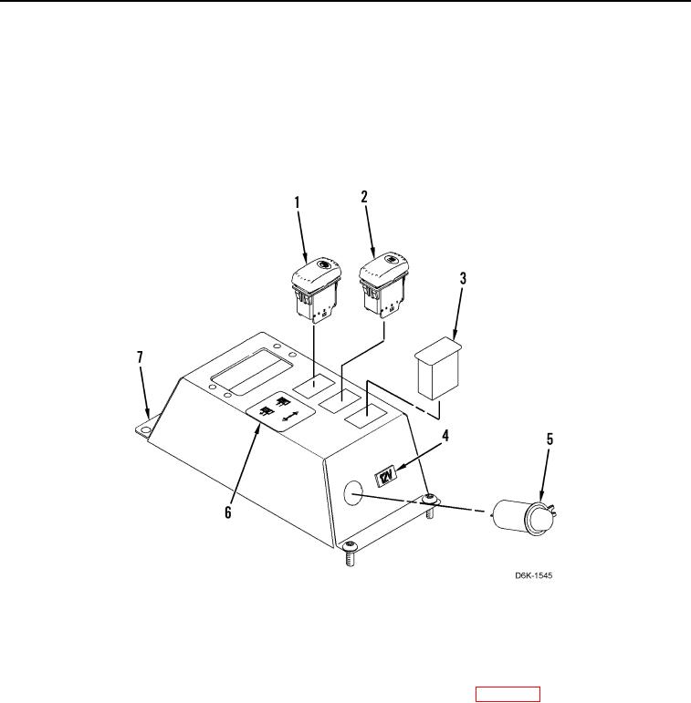
7. Remove winch free-spool switch (Figure 3, Item 1), winch brake switch (Figure 3, Item 2), switch blank
(Figure 3, Item 3), 12V label (Figure 3, Item 4), 12V receptacle (Figure 3, Item 5), and control label (Figure 3,
Item 6) from winch control panel (Figure 3, Item 7).
Figure 3. Winch Control Handle Panel Components.
0217
END OF TASK
CLEANING AND INSPECTION
000217
Clean and inspect all parts IAW Mechanical General Maintenance Instructions (WP 0282).
END OF TASK