
6
TM 5-2410-240-23-3
FIELD MAINTENANCE
-
WINCH OPERATION CONTROL HANDLE REPLACEMENT
0217
Removal, Cleaning and Inspection, Installation
INITIAL SETUP
References
Tools and Special Tools
0
0
Tool Kit, General Mechanic's
0
(WP 0289, Item 51)
0
Equipment Conditions
0
Screwdriver Attachment, Torx,
Machine parked (TM 5-2410-240-10)
3/8" Drive, T-30 (S0288)
0
(WP 0289, Item 53)
0
Drawings Required
0
Materials/Parts
TM 5-2410-240-24P, Figure 98
0
0
Rag, wiping (WP 0290, Item 21)
0
Estimated Time to Complete
0
Tag, marker (WP 0290, Item 30)
0
0.5 Hr
0
REMOVAL
000217
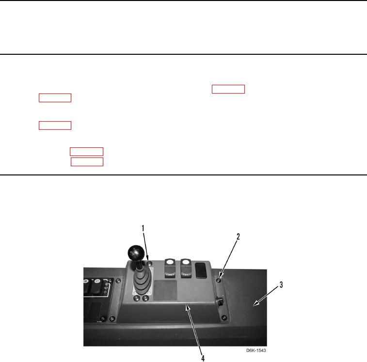
1. Remove eight screws (Figure 1, Items 1 and 2) and winch control panel (Figure 1, Item 4) from console
(Figure 1, Item 3).
Figure 1. Winch Operation Control Handle Panel.
0217